A Robot Waiter That Can Carry Drinks
Abstract
Have you ever seen a waiter balance an entire tray of drinks without spilling any? How do they do it? Do you think you could build a robot waiter that can do the same thing? In this project, you will learn how to build a self-balancing robotic tray. You can incorporate the auto-leveling tray into one of our many other robotics projects, like the Bluebot or robotic arm.
Summary
Previous Arduino experience is recommended. See our How to Use an Arduino page for tutorials.
A kit is available from our partner Home Science Tools®. See the Materials section for details.
No issues

Objective
Build and program a self-balancing robotic platform.
Introduction
You are probably pretty good at balancing. You have likely known how to walk without falling over since you were a little kid! However, learning to balance is not easy - babies and toddlers need lots of practice (and fall over a lot) before they can learn to walk. You can also probably easily carry a glass of water around without spilling it, but that is a difficult task for a toddler, which is why little kids usually get cups with lids!
Humans can balance in part thanks to proprioception - our body's ability to sense its own position and movements. Balance organs in your inner ear (the vestibular system) tell your brain when your head is upright, and stretch receptors in your muscles tell your brain when your muscles are stretched or relaxed. Thanks to these systems, we "know" when we are standing upright or when a glass of water we're holding is vertical and will not spill. We can even do this without relying on vision.Try it out - close your eyes and tilt your head to the side, or rotate your wrist so your palm is face up and then face down. You can sense the orientation of your different body parts even if you cannot see them or the room around you.
So, that's great for humans - what about robots and electronic devices? How does your phone know to rotate the screen when you tilt it from a vertical to horizontal position? How does a video game controller know when you shake it or tilt it? These devices use a type of electronic sensor called an accelerometer. An accelerometer acts sort of like the vestibular organs in your inner ear. As the name implies, accelerometers can sense acceleration, or a change in velocity. However, accelerometers can be a little confusing. They can detect linear acceleration, or acceleration in a straight line, like a car accelerating from a stoplight. However, they can also detect acceleration due to gravity - the pull we feel from Earth's gravitational field. This means that an accelerometer sitting perfectly still on a table will report zero acceleration in the horizontal direction, but 9.81 m/s2 acceleration in the vertical direction (acceleration due to Earth's gravity at the surface), not zero. Watch this video to learn more about accelerometers, how they work, and how to use one with an Arduino, the microcontroller you will use for this project:

So, if you can use an accelerometer to detect which way gravity is pointing (and therefore figure out which way is "up"), how do you build a robotic system that can stay upright? We need something that can move to a specified position, and that is where servo motors come in. Watch this video to learn more about servo motors and how to control one with an Arduino:

To design a robotic system that can automatically stay upright, we need to connect our servo motor and accelerometer somehow. We will do that using a feedback loop, also called feedback control. Your body has automatic feedback loops to stay balanced. Imagine that you trip or stumble while you are walking. Your sensory system detects that you have tripped and sends this information to your brain. Your brain sends commands to your muscles to bring your body upright again. Your sensor system detects your body's new position, and so on (that is why it's called a "loop"). In our robotic system, the accelerometer is like the sensory system, the servo motor is like the muscle, and the Arduino is like the brain.
There are many different types of feedback control. The simplest type is on/off control, which is how many basic thermostats work. When you turn the heat on in your house, you set a desired temperature, the setpoint. The thermostat measures the actual temperature in the house. If this temperature drops below the setpoint, it turns the heat on and the house starts to heat up. Once the temperature reaches the setpoint, it turns the heat off, the house will start to cool down again, and the process repeats. This results in the temperature oscillating up and down a little bit, but that is usually OK for a simple system like a thermostat. It is not a great approach, however, for many moving or mechanical systems - for example, cruise control in a car. Imagine that a driver set the cruise control speed to 65 mph on a highway, but the car could only control the speed by fully slamming on the gas pedal or slamming on the brakes! That would result in a very jerky and uncomfortable (not to mention dangerous) ride.
A more gentle approach involves using proportional control. A proportional controller measures the error, or the difference between the setpoint and the actual value (which could be a temperature, velocity, orientation, etc.). Instead of just being fully on or fully off, the control effort is then proportional to the size of the error. For example, if it is really cold in your house, the thermostat knows to turn the heat on full blast. If the car is going really slow, the cruise control knows it needs to really press on the gas. However, if the temperature has almost reached the setpoint, the thermostat can turn the heat on low, or if the car's speed has almost reached the target, it can just press on the gas a little bit. To calculate the size of the control effort, the error is multiplied by the controller's gain:
A gain that is too small may result in a controller that is very slow to respond - you do not want to wait all day for your house to heat up! Increasing the gain can make the controller's response faster, but increasing it too much can make the system unstable - imagine hitting the gas too much and going past your desired speed (this is called overshoot), then hitting the brakes too much and slowing down past the desired speed, and repeating this process - oscillating back and forth without ever actually settling on the setpoint. The process of finding the right gain that works well for a system is called tuning the controller.
In this project, you will first test on/off control, then tune a proportional controller to automatically balance a platform using a servo motor and an accelerometer. Optionally, you can try adding two more types of control to your project: integral and derivative control. Combined proportional, integral, and derivative control is abbreviated PID control. An integral controller exerts effort proportional to the amount of error accumulated over time, and a derivative controller exerts effort proportional to the rate of change of the error. Each term has a different effect (discussed more in the video at the top of this page) and can be useful when tuning your controller for an optimal response - in this case, to avoid spilling a drink!
Terms and Concepts
- Proprioception
- Vestibular system
- Stretch receptors
- Sensor
- Accelerometer
- Acceleration
- Linear acceleration
- Acceleration due to gravity
- Servo motor
- Feedback loop
- Feedback control
- On/off control
- Setpoint
- Proportional control
- Effort
- Unstable
- Overshoot
Questions
- How do humans balance?
- How does an accelerometer work?
- What is feedback control?
- What are some examples of feedback control in both biological and electronic/mechanical systems?
- What do the different terms in a PID controller each do?
Bibliography
- Finio, B. (n.d.). Accelerometer Technical Note. Science Buddies. Retrieved June 11, 2025
- Finio, B. (n.d.). How to Use an Arduino. Science Buddies. Retrieved June 11, 2025
- Science Buddies staff (n.d.). The Engineering Design Process. Science Buddies. Retrieved June 11, 2025
Materials and Equipment 
Recommended Project Supplies
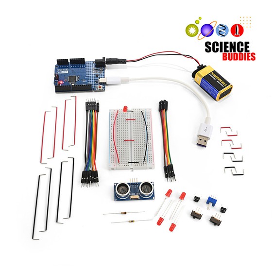
- Electronics Kit for Arduino, available from our partner Home Science Tools®.
- Accelerometer such as the ADXL335.
- The example code in this project is written for the ADXL335, which is an analog accelerometer. You will need to use different code if you purchase a digital accelerometer.
- Most accelerometer breakout boards come with header pins that you need to solder on yourself, so you will need access to a soldering iron.
- Positional servo motor like the SG90, which is a small servo popular for Arduino projects. It will work for balancing a small container of water like a medicine cup. If you want to balance a larger tray with real drinks, you will need to purchase a larger servo.
- Popsicle sticks
- Hot glue gun
- Windows or Mac computer. See this page if you have a Chromebook. Your computer will need:
- Access to the Arduino IDE, either installed local version or web-based editor. Watch this video for a comparison of the two options.
- USB port. The Science Buddies kit comes with a USB-A to C cable. The "C" end plugs into the Arduino and the "A" end plugs into your computer. You will need an adapter or different cable if your computer only has USB-C ports. Watch this video to learn about the different types of cables and adapters.
Disclaimer: Science Buddies participates in affiliate programs with Home Science Tools®, Amazon.com, Carolina Biological, and Jameco Electronics. Proceeds from the affiliate programs help support Science Buddies, a 501(c)(3) public charity, and keep our resources free for everyone. Our top priority is student learning. If you have any comments (positive or negative) related to purchases you've made for science projects from recommendations on our site, please let us know. Write to us at scibuddy@sciencebuddies.org.
Experimental Procedure
- Assemble your circuit as shown in Figure 1.
- Connect the accelerometer:
- Vcc pin to Arduino 3V3 pin. Important - the ADXL335 is powered by 3.3V, not 5V, so make sure you do not connect this to the Arduino 5V pin! If you purchased a different accelerometer, read its datasheet to find its operating voltage.
- GND pin to Arduino GND pin.
- X to Arduino A0 pin.
- Y to Arduino A1 pin.
- Z to Arduino A2 pin.
- Connect the servo motor:
- Orange wire (signal) to Arduino pin 9
- Red wire (power) to Arduino 5V pin
- Brown wire (ground) to Arduino GND pin
- Connect the accelerometer:
 Image Credit: Ben Finio / Science Buddies
- Test your servo and accelerometer individually to make sure they are wired properly.
- You can test the servo using the example code that comes with the Arduino IDE under File→Examples→Servo→Sweep. This should make the servo oscillate back and forth.
- You can test the accelerometer using our accelerometer example code available on this page. This should print out the analog readings from all three accelerometer axes.
- Build a tray or platform for your servo motor (Figures 2 and 3).
- Attach one of the servo horns to the servo shaft.
- Use popsicle sticks and hot glue to build a small tray and attach it to the shaft.
- Mount the accelerometer to the bottom of the tray. In our example, the positive Z axis is facing downward, the X axis points to the side, and the Y axis points along the axis of rotation (aligned with the motor shaft). Our example code uses the reading from the X axis to detect tilt. If you mount your accelerometer differently, you may need to use a different axis.
- Attach another popsicle stick to the base of the servo motor to make an "arm." This will make it easier to hold and rotate the servo motor.
- If needed, use zip ties or twist ties to keep the wires organized.
 Image Credit: Ben Finio / Science Buddies
 Image Credit: Ben Finio / Science Buddies
- Now you are ready to test simple on/off control.
- Download the auto_leveling_on_off example code. Read through the commented code so you understand how it works.
- Unplug the control wire for your servo motor - this will prevent the servo from moving.
- Upload the code to your Arduino.
- Open the serial monitor in the Arduino IDE (Tools→Serial Monitor).
- Watch the output as you rotate the platform and tilt the accelerometer.
- Hold the platform as level as possible and look at the output. The ADC reading will still fluctuate slightly - it is nearly impossible to hold the platform perfectly still, and the accelerometer is very sensitive!
- Write down the average or typical value that you see.
- In the code, change the
setpointvariable so it is equal to the value you just recorded. - Comment out the
serial printlines in the code. These commands slow the program down and will affect the speed of your control loop. - Re-upload the code and reconnect your servo motor control wire. Hold the servo motor with your hand. Watch what happens.
- Your servo motor might rapidly oscillate back and forth because it is overshooting the set point. Can you think of ways to fix this problem?
- Try adding a
delayat the end of yourloopfunction. Experiment with different times for the delay. Can you find a time that prevents overshoot but does not make the servo move too slowly? - Try increasing the range for which the motor will stop moving (this is called a deadband). The way the code is written now, the accelerometer reading must be exactly equal to the setpoint for the servo to stop moving. Otherwise, the feedback loop will always try to increase or decrease the servo motor angle to hit the right setpoint. For example, change the line of code
if(ax_ADC < setpoint)toif(ax_ADC < setpoint - 10). That way, the motor will only start to rotate if the accelerometer reading is 10 less than the setpoint. Similarly, you can change else if(ax_ADC > setpoint)to elseif(ax_ADC > setpoint + 10). Experiment with different values other than 10 (hint: use a variable instead of a hard-coded number, so you do not have to change the number in two places). Can you find a value that works well and still keeps the tray reasonably level?
- Try adding a
- If you can get the platform to stay level, now try slowly rotating your wrist while holding the base of the servo motor. Does the platform stay level? How quickly can you rotate your wrist?
- Now try a proportional controller.
- Download the auto_leveling_proportional example code. Read through the commented code so you understand how it works.
- Upload the code to your Arduino. Again, hold the servo motor and watch what happens.
- If the servo oscillates back and forth, tune your controller. Try decreasing the controller's gain (the
Kpvariable in the code). - Re-upload the code. Keep decreasing the
Kpvalue until the servo stops oscillating. - Try slowly rotating your wrist while holding the servo. How fast does the platform respond? Try moving your wrist more quickly. What happens?
- Can you increase the value of
Kpby small amounts to make the system respond faster? How much can you increase it without causing the system to be unstable again?
- Once you are confident that your controller can keep the platform level, experiment with balancing a small amount of water (Figure 4).
- Fill a small container like a medicine cup with a little bit of water and place it on the platform.
- If the bottom of the container is slippery, you can add a few dabs of hot glue to give it more friction (let the glue dry on the container, do not actually glue it to the platform).
- Keep the water away from your Arduino in case of a spill.
- Can you move your hand around and rotate your wrist without spilling the water, just like a real waiter? Does further tuning your controller gain help?
- There are many other things you can do with this project. See the Variations section for more ideas.
 Image Credit: Ben Finio / Science Buddies
Ask an Expert
Variations
- Try adding integral and derivative control to make a PID controller. Download auto_leveling_PID example code to help you get started. You will need to do more research about PID controllers and the effects of the integral and derivative terms. There are strengths and weaknesses to each type. We recommend starting with 0 for the integral and derivative gains and just tuning the proportional controller, then adding integral and derivative control one at a time.
- Can you mount an auto-leveling platform on an Arduino-controlled self-driving car? Can the car keep the platform level when driving up or down hills?
- Can you attach a self-leveling platform to a robotic arm that has additional servo motors? Can you use input from multiple accelerometer axes to keep the platform level even when the robotic arm moves around in three dimensions instead of rotating about a single axis?
- Can you combine the two projects listed above and mount a robotic arm on a robotic car? Maybe you can even make an autonomous robot waiter that can drive around and serve drinks or snacks at your next party!
Careers
If you like this project, you might enjoy exploring these related careers:


Contact Us
Our kits are developed in partnership with Home Science Tools®. If you have purchased a kit for this project, Home Science Tools® is pleased to answer any questions.In your email, please follow these instructions:
- Include your Home Science Tools® order number.
- Please describe how you need help as thoroughly as possible:
Examples
Good Question I'm trying to do Experimental Procedure step #5, "Scrape the insulation from the wire. . ." How do I know when I've scraped enough?
Good Question I'm at Experimental Procedure step #7, "Move the magnet back and forth . . ." and the LED is not lighting up.
Bad Question I don't understand the instructions. Help!
Good Question I am purchasing my materials. Can I substitute a 1N34 diode for the 1N25 diode called for in the material list?
Bad Question Can I use a different part?
Contact Support
Related Links
- Science Fair Project Guide
- Other Ideas Like This
- Robotics Project Ideas
- Electricity & Electronics Project Ideas
- My Favorites